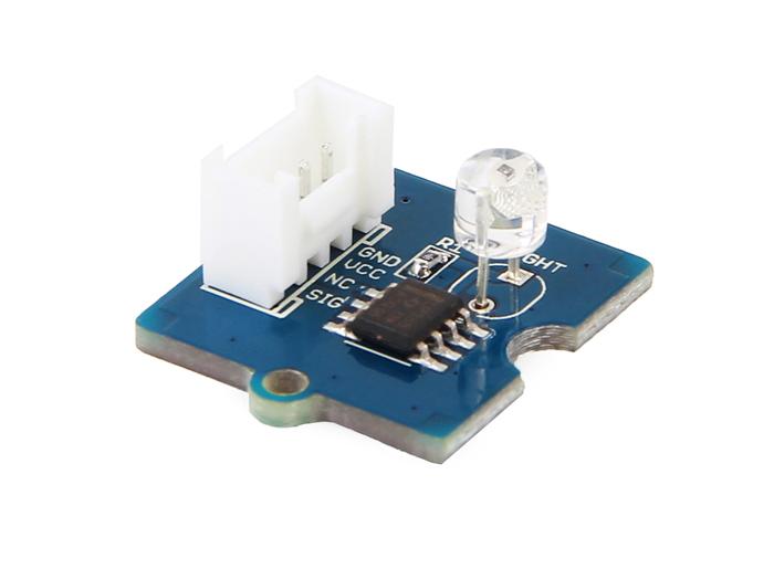
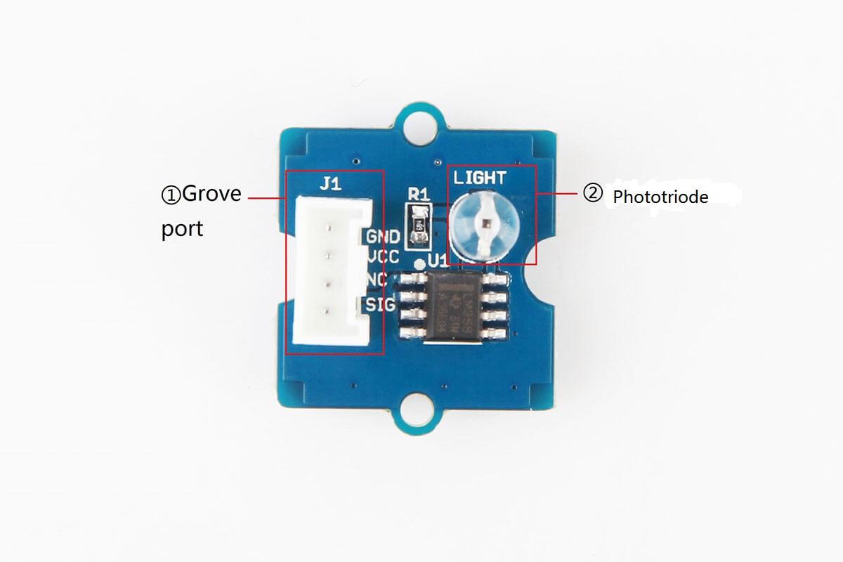
The Grove - Light Sensor v1.2 is updated version of Grove - Light Sensor 1.0 which is aimed at measuring light levels in daily life. It is an analog module and output various electrical signals which can be converted to different ranges(that depends on the Analog-to-Digital-Converter on your controller board. For example, it will output 0-255 for an 8-bit ADC). It integrates a high-sensitive and reliable phototriode, and is interfaced with Grove port which will save you a lot of work in the wiring.
| Product reversion | Release date | Support status | Notes |
| Grove - Light Sensor 1.0 | April 28 2013 | Supported | |
| Version 1.2(current version) | Dec 2015 | Supported |

| Operating voltage(V) | 3 volts-5 volts |
| Operating current(mA) | 0.5 mA-3 mA |
| Response time | 20-30 milliseconds |
| Peak Wavelength | 540 nm |
| Phototriode | LS06-MΦ5(datasheet) |
| Weight | 4 g |
Note you can get more Information about light level(illumination) in daily life here.
This part will show you some basic examples as a hint for applications on different development board families.
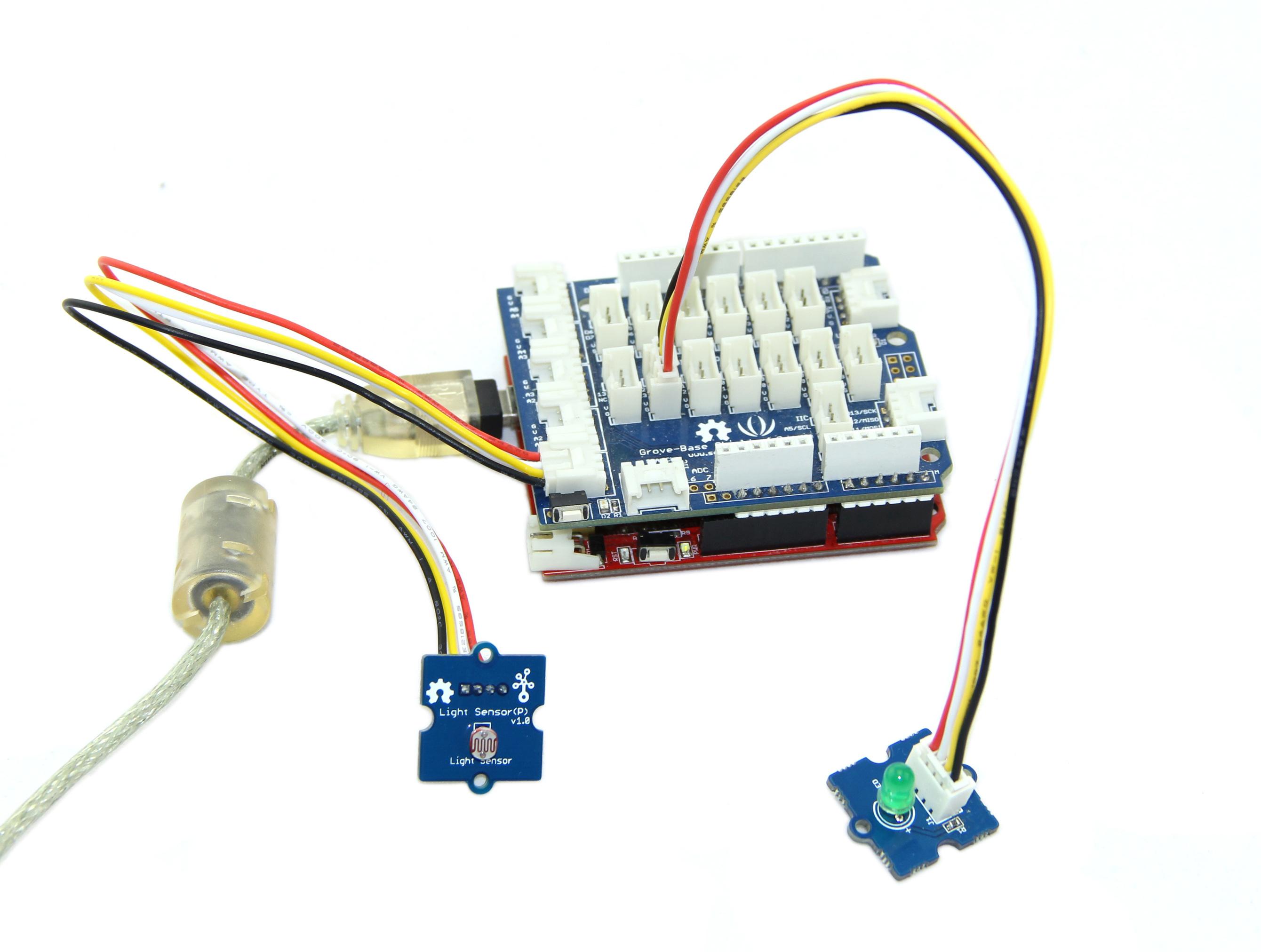
/* Grove - Light Sensor demo v1.2
*
* signal wire to A0.
* By: http://www.seeedstudio.com
*/
#include <math.h>
const int ledPin=9;                 //Connect the LED Grove module to Pin12, Digital 12
const int thresholdvalue=10;         //The threshold for which the LED should turn on.
float Rsensor; //Resistance of sensor in K
void setup() {
  Serial.begin(9600);                //Start the Serial connection
  pinMode(ledPin,OUTPUT);            //Set the LED on Digital 12 as an OUTPUT
}
void loop() {
  int sensorValue = analogRead(0);
  Rsensor=(float)(1023-sensorValue)*10/sensorValue;
  if(Rsensor>thresholdvalue)
  {
    digitalWrite(ledPin,HIGH);
  }
  else
  {
  digitalWrite(ledPin,LOW);
  }
  Serial.println("the analog read data is ");
  Serial.println(sensorValue);
  Serial.println("the sensor resistance is ");
  Serial.println(Rsensor,DEC);//show the light intensity on the serial monitor;
  delay(1000);
}
# GrovePi+ & Grove Light Sensor & LED

import time
import grovepi

# Connect the Grove Light Sensor to analog port A0
# SIG,NC,VCC,GND
light_sensor = 0

# Connect the LED to digital port D4
# SIG,NC,VCC,GND
led = 4

# Turn on LED once sensor exceeds threshold resistance
threshold = 10

grovepi.pinMode(light_sensor,"INPUT")
grovepi.pinMode(led,"OUTPUT")

while True:
    try:
        # Get sensor value
        sensor_value = grovepi.analogRead(light_sensor)

        # Calculate resistance of sensor in K
        resistance = (float)(1023 - sensor_value) * 10 / sensor_value

        if resistance > threshold:
            # Send HIGH to switch on LED
            grovepi.digitalWrite(led,1)
        else:
            # Send LOW to switch off LED
            grovepi.digitalWrite(led,0)

        print "sensor_value =", sensor_value, " resistance =", resistance
        time.sleep(.5)

    except IOError:
        print "Error"
cd GrovePi/Software/Python/
sudo python grove_light_sensor.py